Most passive membrane properties can be calculated from a membrane test performed in voltage-clamp mode. This is usually done by rapidly voltage-clamping between two voltages (usually -70 mV to -80 mV and back) and inspecting the membrane currents which result from it. This is all it takes to calculate holding current (Ih), membrane resistance (Rm), access resistance (Ra), and capacitance (Cm). In advanced cases a secondary voltage-clamp ramp is performed to produce an enhanced measurement of capacitance.
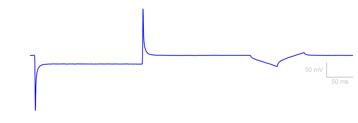
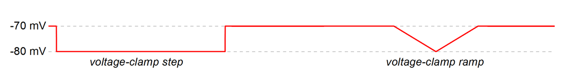
Membrane test protocol: The command voltage (lower trace) rapidly steps between two voltages and the resulting current changes as a result. Capacitive transients (the large downward and upward deflections) are also produced as a result. This membrane test protocol also contains a voltage-clamp ramp for enhanced capacitance determination.
Holding Current
Steady state current is the membrane current before the hyperpolarizing voltage step. In the example above, it is the level of the blue trace at its far left point.
Membrane Mesistance
Membrane resistance (Rm) is calculated from the difference in the steady-state current before and during the voltage-clamp step using Ohm’s Law. If a 10 mV hyperpolarizing step (ΔV = 10 mV) produces a 100 pA current change (ΔI = 20 pA), then R = ΔV/ΔI so Rm = 10 mV / 20 pA = 50 MΩ.
Access Resistance
Access resistance (Ra) is inversely proportional to the height of the peaks (capacitive transients). At experiment time, your goal is to ensure Ra is low (resulting in large peaks) and stable (resulting in peaks whose height does not change over time).
Capacitance
⚠️ TODO
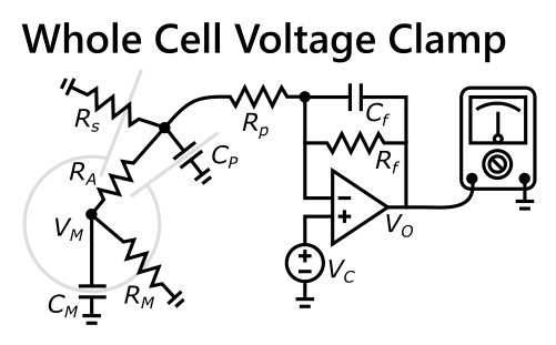
Membrane Test Circuit
🤓 Nerd Alert: Access resistance (Ra) is calculated from the theoretical instantaneous peak of the capacitive transients. In practice just measuring the peaks allows often a good-enough estimation of Ra (especially if your goal is just to access Ra stability over a time course), but deriving this value perfectly involves curve-fitting (to the simple exponential decay curve) and back-calculating the actual peak (which was partially degraded by the based low-pass filter). This is not really important for Ra itself, but since Ra is used to calculate Rm it is critically important that Ra be calculated in this way if Cm is to be accurate. In this case, Cm is calculated using the decay constant (Tau, τ) of the capacitive transient (this is what ClampEx does to calculate Cm), but this is highly sensitive to small changes in Ra and also highly sensitive to the hardware lowpass filter. An alternative method of Cm determination made from voltage-clamp ramps is shown here after the voltage-clamp step. This form of Cm determination is often more accurate, especially for small cells. It is also highly insensitive to the presence of sIPSCs and sEPSCs. For more information see Exploring the Voltage-Clamp Membrane Test.